In a permanent magnet rotating machine, when a symmetric sinusoidal current is passed through the three-phase winding, a sinusoidal distributed rotating magnetic field is generated in the air gap. Similarly, after a three-phase current is applied to a permanent magnet linear motor, a magnetic field is also generated in the air gap, ignoring the end effect, and the magnetic field is also sinusoidally distributed in a straight line, but the magnetic field is a translational traveling wave magnetic field, see figure 1. The interaction between the traveling wave magnetic field and the secondary magnetic field produces an electromagnetic thrust that causes the primary and secondary to produce a horizontal linear relative motion. The part that generates electromagnetic force is the part where the primary and the secondary are coupled [2]. Relationship between structure and thrust of permanent magnet linear motor Thrust density of permanent magnet linear motor Under the condition of certain material and cooling conditions, the rated torque of the designed rotating motor is basically proportional to the volume of the motor. The rated thrust of the linear motor is also the same, and the ratio of the rated thrust FN of the motor and the effective volume V (ie the volume of the primary and secondary coupling parts) is defined as the thrust density. F: F = FXV (1) F has a maximum value. If the thrust density of a motor reaches the limit value, the magnetic circuit parameter of the motor is the optimal parameter. For the short primary permanent magnet linear motor discussed herein (see Figure 2), the effective width a is the portion of the coupling width of the primary and secondary magnetic steel. The effective length b is the length of the primary core. The effective height h includes the primary core height, the secondary magnetic steel thickness, and the air gap size. The effective width a and the structure of the thrust rare earth permanent magnet linear motor have symmetry in the y direction (width direction). The secondary magnetic steel is uniformly magnetized in the y direction. If the slight change of the shape of the y-direction of the magnetic steel and the magnetic leakage at the end are not considered, the distribution of the internal magnetic field can be considered to be constant along the y direction. That is, the thrust of the motor is proportional to the lateral width a. A longitudinal section of the linear motor can be taken in the width direction for analysis, and the result is a linear motor with an effective width per unit length. The calculation result is multiplied by the actual effective width of the motor, which is the actual analysis result of the motor. Therefore, the rated thrust of the linear motor can be expressed by the formula (2): where f = a ΔFa (2) where a is the lateral effective width of the motor, and ΔFa is the rated thrust of the linear motor having the unit lateral effective width. The effective length b and the effective length b of the thrust can be measured in units of the number of motor poles p. The design motor adopts a single-layer winding structure. When the end effect is neglected, the primary pole number is increased, and the magnetic circuit parameters and the magnetic field distribution characteristics are not changed, that is, the optimized magnetic circuit parameters of the motor are not changed. Based on this structural feature of the permanent magnet linear motor, if only the primary pole number is increased, the thrust of the motor will increase linearly and the magnetic circuit parameters can be optimized. The motor thrust is roughly proportional to the number of motor poles. It can be expressed as: F = P2 △ Fx (3) where P is the number of poles of the motor, and ΔFx is the rated thrust of the unit width of the two-pole motor. As the number of motor stages increases, the error of equation (3) becomes larger and larger. When the number of poles of the motor is 16, the error rate is 1.44%. But in general, the formula error rate is small and can be used for the preliminary design of the motor. The effective height h and the thrust effective height h include the primary core height, the secondary magnetic steel thickness, and the air gap size. The greater the core height and the thickness of the secondary magnetic steel, the more the magnetic energy material is represented, and the greater the thrust. The air gap is the place where the primary and secondary energy exchange. The larger the air gap, the smaller the thrust. The effective height h is closely related to the motor thrust, and there is no simple rule to follow. Generally, the effective height h needs to be optimized. Design method of permanent magnet linear motor The conventional design method of permanent magnet linear motor refers to the design method of permanent magnet rotating motor. In the design, the basic conditions must be determined first, including rated voltage U, frequency f, and maximum current capacity I. It is also necessary to clarify the performance indicators to be achieved by the motor design: rated thrust FN, maximum thrust Fmax, and the like. Then according to the given conditions and objectives, determine the specific parameters of the primary, secondary and air gap of the motor, the whole design process is more complicated. According to the analysis in Section 3, the concept of a two-pole unit linear motor is introduced to simplify the motor design process. The conclusion analyzes the influence of geometrical dimensions of flat permanent magnet linear motor on motor thrust by analogy of the concept of thrust density of rotating electric machine. On this basis, the design method of the two-pole unit linear motor is proposed, which simplifies the design process of the flat-plate permanent magnet linear motor, and provides a basis for the serial design of the linear motor in the future. Finally, according to the design method, a prototype design with a rated thrust of 3000N was completed. Through the experimental test of thrust and positioning force, the performance of the prototype is basically consistent with the design performance. (Finish)
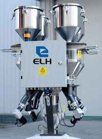
In this category, Granule Mixing equipment
and Powdered Material Blending equipment are included. In granule mixing
sub-category, gravimetric batch blender EGB series
with output up to 1680Kg/hr for up to 8
components and gravimetric continuous blender ECB series with output up to 1200Kg/hr
for up to 4 components, high capacity screw
type plastic color mixer ESM series with loading capacity up to 1000Kg, and blade
type plastic color mixer EM series with loading capacity up to 300Kg are
included.
In the sub-category of powdered material
blending, vertical type high speed heating mixer EHM series with 14 models and
volume up to 1000L, vertical type cooling mixer ECM series with 5 models and
volume up to 1600L, vertical type heating and cooling combined mixer EHCM
series with 5 models and volume up to 800L and 1600L for heating and cooling
respectively, horizontal type heating and cooling combined mixer EHCM-H series
with 4 models and volume up to 800X2L and 4000L for heating and cooling respectively
are included.
Vacuum Visual Vacuum Conveyors,Electric Vacuum Feeding Machine,Pneumatic Vacuum Feeding Device,Vacuum Feeder,Vacuum Feeding Equipment,Vacuum Powder Feeder ELH Machinery Co., Ltd , http://www.elh-machinery.com