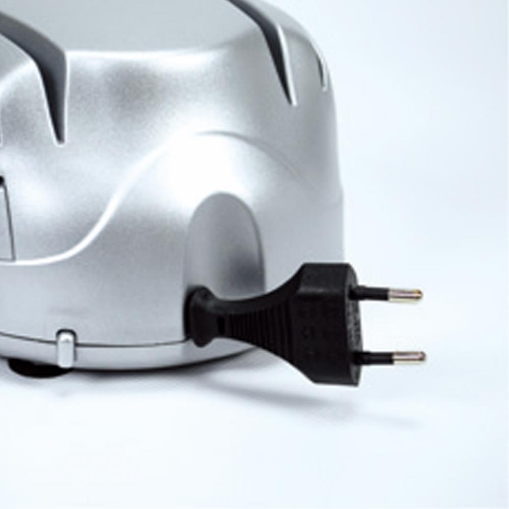
General specifications
Base speed: ON/OFF Non-slip feet: 4pcs
Sharpening wheels: 2
Technical specifications
Power: 60W Frequency: 50/60 Hz
Voltage: 220-240V Cord length: 1 m
Design specifications
Material body: HIPS
Surface finishing: injected color
Cord storage: Yes
Approvals
GS/CE/CB/LVD/EMC/ROHS/REACH/ERP
Kitchen Knife Sharpener,Knife Sharpener As Seen On Tv,Knife Sharpener Electric Reviews,Knife Sharpener Edge Pro Polishing Housoen Electric Manufacture Co., Ltd. , https://www.housoenappliances.com
The motion analysis has been more mature, but its force analysis has not yet formed a general method. With the development of production, the rotational speed of GLM applied in production practice is getting higher and higher, so the dynamic static analysis of a general GLM is sought. The method of (hereinafter referred to as force analysis) is necessary.
Compared with the force analysis of the planar linkage mechanism, the force analysis of the GLM has its own unique difficulties. In the force analysis of the plane connecting rod set, it is known from the static deterministic condition of the rod group that the 2P restraining reaction forces requested on the P moving low pair can be from 3N (N is the number of rods in the rod group) In the balance equation, the solution is obtained. In the gear connecting rod set, there is a complex hinge. The reaction force of the gear pair has only one independent component, and its direction is unknown. For this problem, this paper will analyze the type of transformation analysis. A general method, which is easy to solve and easy to program on the balance force or balance torque and the restraining reaction force in the motion pair.
1 The force analysis of the complex hinges In the components of the complex hinge, there is often one gear. In the double pole group shown, the inner hinge B is a complex hinge. The force analysis of the complex hinge is not considered here. It has the known external force and inertial force, which does not affect the generality of the discussion. Let the component of the reaction force acting on the external hinge be XaYaXc and Yc, and the force component of the gear 3 acting on the hinge B be Fbx and Fby, and now the internal reaction B acts on the rod 1 and the rod 2 on the rod 1 and 1R1RLrL The inner hinge B can be regarded as the hole on the two members is connected by a round pin, and the external force acting on it (ie FSx and FSy) can be regarded as acting on the round pin by the force balance condition of the round pin. Two equations can be used to obtain RB1R1rX2RbY2. If the round pin at the inner hinge is not in the shape of the optical axis, but is fixed to a certain rod, such as the dynamic analysis of the force analysis of the rod 1 2 force, through a certain number of virtual The motion parameters decompose the structure of the gear connecting rod set into a series of single-member and double-rod groups, so that the motion analysis problem of GLM is transformed into the motion analysis problem of single-member and double-bar group, forming a GLM general motion analysis. method.
When the motion analysis of the gear link rod set is carried out by the type conversion method, the outer sub-motion parameters of the rod group are known, and the inner sub-motion parameters are to be determined. The force analysis of the gear connecting rod set is very different from the motion analysis. The internal and external moving force parameters of the rod group are unknown, and the known conditions are only the external force, external force, gravity, inertia acting on the mechanism. Force and inertia force couple.
Any gear linkage rod set satisfies the formula: 3n-2p-pH=0, which only shows that the gear connecting rod set has motion certainty, and also shows that the gear connecting rod set has static certainty, ie: each The component can list three independent force balance equations. Each low pair has 1 component and the two component forces in the direction are unknown. Each gear height pair has only one independent component. The unknown component is (2p+pH). The unknown force can be obtained from the 3n equilibrium equations. It is found that when GLM performs force analysis, there is also a type conversion problem. If in (2p+Ph) constrained reaction forces, virtual m (ie, GLM type conversion number) When the force is known, the force balance condition of the rod group is converted into (2p+pH) unknown force, and the number of unknown forces is now (2p+ph-m). At this time, the rod group is used as the whole system. It is said that the balance is lost, so there is a need for m additional balancing forces or balancing moments in the system, so that the system is balanced, and the number of unknown forces is restored to (2p+Ph).
The force calculation of the gear connecting rod set is transformed into several force calculation problems of single-joint and double-bar linkages, and the analysis process is simplified. There are virtual units (ie, the components on which virtual know-how is) And a constraining unit (ie, a member to which a balancing force or a balancing torque is attached). The result of the force calculation of the rod group is: when the additional balance force or balance moment is zero, the true value of the virtual force system is obtained, which is the identity condition of the force analysis.
The gear link rod set as shown is composed of a solid wire member 1 23, and the rotating pair AD and the gear high pair e are external motion pairs of the rod group. In order to make the force decomposition route more concise, not to draw all known external forces and inertial forces, this does not affect the general relationship between the 3 force analysis and the motion analysis. Since the force analysis and motion analysis of the gear link rod set Type conversion is divided into virtual units, constrained units and double-bar groups, so they must have inherent interrelationships.
In the research, it is found that the gear connecting rod set is the same as the plane connecting rod set, and its force analysis and motion analysis are uniform and reciprocal, that is, in the transformation, the force conversion and motion analysis type conversion number m can be equal. The reciprocity of the reciprocal force analysis and the motion analysis operation process of the force analysis and motion analysis refers to the structural decomposition route of the force analysis and the number of structural decomposition routes of the motion analysis are 2 Lin Yongshui et al. Force analysis of parasitic gear linkages. Mechanical design and research 3 Lin Yongshui and so on. Force Analysis of Common Gear Linkage Rod Sets AI. Proceedings of the 5th National Institutional Transmission Annual Conference C.1992 Appears the same C-conditions of your 9 forces d is the 1 constraint unit with the force of the road dnicPublishingHouse.Allrights 3 Freedom The 10-pole mechanism is a complex and universal multi-rod mechanism model. It is obvious that the requirements of common scroll compressors can only be met under certain conditions (such as the geometric characteristics of the kinematic chain, the motion characteristics of the revolution, and the force). The characteristics of the transmission, the self-stabilizing characteristics of the meshing, etc., so the essential constraints of the scroll compressor will become the object of further research. In fact, "revolutional translation" is generally considered to be a major feature of the scroll compressor. Therefore, the anti-rotation mechanism is always used to limit its movement, but it can be seen from the above diagram of the mechanism that as long as the relative motion between the main and driven scrolls can be meshed point by point to form a continuous inhalation, compression, and discharge. Air chamber can meet the conditions of compressed gas. 2 Conclusion From the viewpoint of mechanical structure, this paper studies the drive mechanism and the anti-rotation mechanism as a unified movement as a whole. The unified structural model of various mechanisms of the rotary compressor reveals the evolution process of the 10-bar mechanism to various common scroll compressors, and gives the evolution conditions and paths. At the same time, several new types of scroll compressors are also given. The structure, through the analysis of the motion of the mechanism, expands our understanding of the type of scroll compressor mechanism and the constraints of the motion constraints. These will help us to systematically research and innovate the design of the scroll compressor.
5丨9丨10丨 (Continued from page 754)


