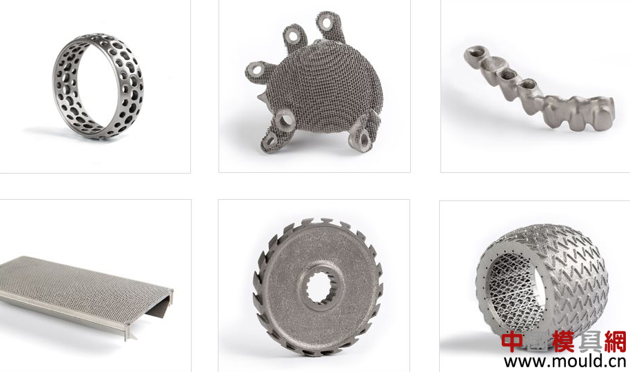
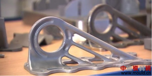
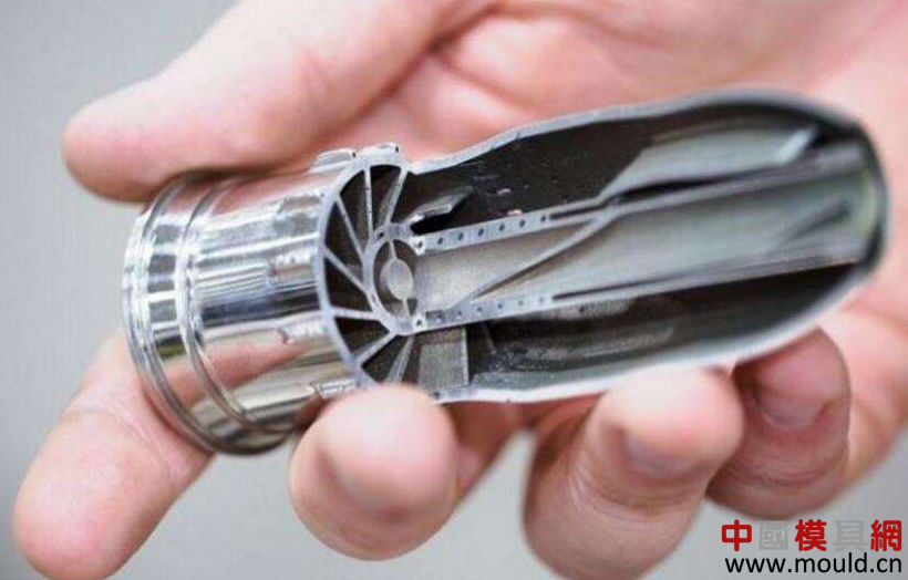
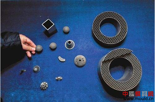
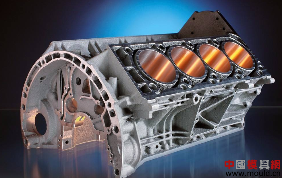
With the rapid advancement of science and technology, the mechanical processing industry continues to grow. The rapid prototyping technology, especially laser 3D printing technology, has played an increasingly important role in the mechanical processing industry, and has gradually been widely used in the manufacturing industry, becoming an integral part of today's machinery manufacturing industry. 3D printing technology is rapidly changing our traditional production methods and lifestyles. The 3D printing technology of metal parts as the most advanced and most promising technology in the entire 3D printing system is an important development direction of advanced manufacturing technology. Metal 3D printing technology is divided into three categories according to the addition of metal powders: (1) The laser is used to irradiate the pre-spread metal powder, that is, the metal part is completely covered with the powder after it is molded. This method is currently widely used by equipment manufacturers and research institutes, including Direct Metal Laser Sintering (DMLS), Selective Laser Melting (SLM), and LC (Laser Cusing); (2) The powder flow delivered by the laser irradiation nozzle is used and the laser is operated simultaneously with the powder (Laser Engineered Net Shaping, LENS). This method is currently used more at home; (3) Electron beam melting of pre-spreading metal powder (Electron Beam Melting, EBM), this method is similar to the first principle, but the use of different heat sources. The selective laser melting technology is an important part of the metal 3D printing field. It adopts a fine focusing spot to quickly melt 300-500 meshes of preset powder materials, and can almost directly obtain functional parts with arbitrary shapes and full metallurgical bonding. Density can reach nearly 100%, size accuracy of 20-50 microns, surface roughness of 20-30 microns, is a promising rapid prototyping technology, and its application has been expanded to aerospace, medical, automotive , molds and other fields. At present, the research and development of SLM equipment has become a hot spot in the field of rapid prototyping at home and abroad. SLM molding equipment SLM equipment generally consists of optical circuit units, mechanical units, control units, process software, and protective gas seal units. Optical path units include fiber lasers, beam expanders, mirrors, scanning galvanometers, and F-Theta focusing lenses. The laser is the most important part of the SLM equipment and directly determines the molding quality of the entire equipment. In recent years, almost all SLM devices use fiber lasers, which have the advantages of high conversion efficiency, reliable performance, long life, and beam mode close to the fundamental mode. Because the quality of the laser beam is very good, the laser beam can be condensed into a very fine beam, and its output wavelength is short. Therefore, the fiber laser has extremely obvious advantages in the laser selective melting and rapid prototyping of precision metal parts. The beam expander is an optical component that is indispensable for the beam quality adjustment. The beam expander is used to enlarge the beam diameter, reduce the beam divergence angle, and reduce energy loss. The scanning galvanometer is driven by a motor and is controlled by a computer. The laser spot can be precisely positioned at any position on the processing surface. In order to overcome the distortion of the scanning galvanometer unit, a dedicated flat field F-Theta scanning lens must be used so that the focused spot has uniform focusing characteristics within the scanning range. The mechanical unit mainly includes powder spraying devices, forming cylinders, powder cylinders, and molding chamber sealing equipment. The quality of powder coating is a key factor influencing the quality of SLM molding. At present, there are mainly two types of powder coating devices in the SLM equipment, namely the powder coating roller and the powder coating roller. The forming cylinder and the powder cylinder are controlled by the motor. The precision of the motor control also determines the forming precision of the SLM. The control system consists of a computer and multiple control cards. The laser beam scanning control is to send a control signal from the computer to the scanning galvanometer through the control card to control the movement of the X/Y scanning mirror to realize the laser scanning. The equipment control system completes the machining operations on the parts. It mainly includes the following functions: (1) System initialization, status information processing, fault diagnosis, and human-computer interaction functions; (2) Various controls on the motor system, providing motion control of formed pistons, powder supply pistons, and powder roller (3) control the scanning galvanometer, set the scanning galvanometer's movement speed and scanning delay, etc.; (4) set various parameters of the automatic forming equipment, such as adjusting the laser power, forming cylinder, powder cylinder up and down parameters, etc. . (5) Provide coordinated control of the five motors of the molding equipment and complete the machining operations on the parts. According to the needs of the SLM process, there are three main types of professional software involved: slicing software, scan path generation software, and device control software. The slicing process implemented by the slicing software is one of the key contents of the rapid prototyping software, and its function is to convert the 3D CAD model of the part into a 2D slicing model and obtain layered cross-section outline data. In the SLM process, the most basic operation is to control the laser to scan. Since the section information obtained by delamination is outline data, it needs to be internally filled. The function of the scan path generation software is to generate a fill scan path from the outline data. The master control software mainly controls the molding process, displays the processing status, and then realizes human-machine interaction. SLM molding principle The basic principle of SLM technology is: first use the pro/e, UG, CATIA and other three-dimensional modeling software to design the three-dimensional solid model of the part, and then slice the three-dimensional model by slicing software to obtain the outline data of each section. , Generated from the outline data to fill the scan path, the device will follow these fill scan lines, control the laser beam selection area to melt the metal powder materials in each layer, and gradually stacked into three-dimensional metal parts. Before the laser beam starts to scan, the powder spreading device first pushes the metal powder flatly onto the substrate of the forming cylinder. The laser beam then melts the powder on the substrate according to the filling contour line selection area of ​​the current layer, processes the current layer, and then the shaping cylinder descends one layer. With a thick distance, the powder cylinder rises a certain thickness, and the powder spreading device spreads the metal powder on the already processed current layer. The equipment is transferred to the next layer of outline data for processing, and the layers are processed until the entire part has been processed. The entire process is carried out in a processing chamber protected by an inert gas to prevent the metal from reacting with other gases at high temperatures. Outlook for SLM Equipment Looking at the SLM equipment and applications at home and abroad, SLM equipment needs continuous improvement and development in the following aspects. (1) Cost-effective trend SLM equipment is a great innovation and supplement to the current mechanical processing industry, but the high price of SLM equipment has hindered its promotion and application. The price of SLM equipment abroad is about RMB 5 million to 7 million. It does not include follow-up material usage fees. Domestic research institutes or companies generally cannot afford such high costs. In order to better promote and develop, SLM equipment will continue to reduce costs, toward a cost-effective trend. (2) Trends in forming large-size parts Due to the limitation of the laser power and scanning galvanometer deflection angle, the SLM device can form a limited range of part sizes. This makes the SLM device unable to form large-size metal parts, and also limits the popularization and application of SLM technology. Currently, foreign SLM equipment manufacturers are developing large-scale parts molding equipment. For example, M3 equipment developed by Concept Laser Co., Ltd. can already form metal parts with a size of 300×350×300 mm. (3) Trends in combination with traditional processing methods Although SLM technology has many advantages, it also has the disadvantages of high manufacturing cost and poor surface quality of molded parts. Therefore, if we can combine the SLM technology and traditional machining methods, and at the same time bring the advantages of both, it will make the manufacturing technology to a higher level. At present, Matsuura Corporation of Japan has developed the LUMEX Avance-25 metal light modeling and compounding processing equipment, which combines metal laser molding with high-speed and high-precision cutting to realize a composite machining technology. The LUMEX Avance-25 device can alternate metal laser forming and finishing with end mills in a single unit. In this way, dimensional accuracy and surface roughness comparable to those of conventional machining methods are achieved, and complex-shaped parts that cannot be formed by conventional machining methods can also be machined. In addition, this composite machining technology can also significantly shorten the manufacturing cycle, shortening the time for designing and processing a metal part by 61.5%. This technology is bound to be a trend in the future development of SLM equipment. (4) Customized and intelligent trends With the constant weight reduction and integration of various components, customized portable SLM devices will appear in the future. These SLM devices will become practical tools for people's production and work in the future, subvert traditional manufacturing methods, and change people's lifestyles. Spheroidization and warpage are the main defects in the SLM molding process. In order to overcome these defects and produce high-quality metal molded parts, the future SLM equipment needs to have an intelligent process control function. Spheroidization is the accumulation of small defects in each layer of powder melting, and the molding quality of each layer is determined by the process parameters. Therefore, if intelligent real-time monitoring can be realized in the SLM molding process, the process parameters are automatically adjusted to eliminate defects in the event of minor defects, so that molding defects can be avoided and high-quality and high-precision metal parts can be obtained. in conclusion The 3D printing technology of metal parts as the most advanced and most promising technology in the entire 3D printing system is an important development direction of advanced manufacturing technology. SLM equipment generally consists of optical circuit units, mechanical units, control units, process software, and protective gas seal units. Many scientific research institutions and manufacturers at home and abroad have developed more advanced SLM equipment and have mature applications. The development of high-efficiency, cost-effective, large-scale and traditional SLM equipment combined with traditional machining methods is the future direction of metal 3D printing. This equipment is suitable for the grinding processing of the second and third generation of automobile wheel bearings.Adopt PLC+ position control module, double servo control workpiece feed and grinding wheel dressing compensation mechanism respectively.10.4 "touch screen, easy to operate, ball screw and rigid cross roller guide ensure feed precision, feed resolution 0.001 μm10.4 "touch screen, easy to operate, ball screw and rigid cross roller guide ensure feed precision, feed resolution 0.001 μm, repeat precision 0.001 μm. Hub Bearing,Hub Bearing Grinding Machine,Bearing Grinding,Hub Bearing Processing Xinxiang Sunrise CNC Bearing Equipment Co., Ltd. , https://www.cncsunrise.com